


Log flume rides and water attractions present some of the most demanding conditions that photoelectric sensors encounter in any industry. Constant water exposure, submersion risk, high humidity, chemical treatment of the water, temperature variations, and the physical presence of splashing water and foam all conspire to destroy sensors that are not specifically selected and installed for the application. Yet reliable boat detection is fundamental to the safe and efficient operation of these attractions — controlling dispatch intervals, preventing collisions, triggering special effects, and ensuring proper unload sequencing.
This guide covers the selection and installation of industrial infrared photoelectric sensors for log flume and water ride boat detection applications, drawing on the same sensor technology used successfully in major theme park installations worldwide.
Why Industrial Sensors?
Consumer-grade photoelectric products — the types found in garage door openers and basic security systems — are not designed for the conditions of a water ride. They lack the ingress protection, the optical power, and the robust construction needed to survive in constant proximity to water. Industrial-grade infrared photoelectric sensors, by contrast, are engineered for 24-hour operation in harsh environments. They are available in sealed stainless-steel housings with IP ratings appropriate for submersion, they generate powerful infrared beams capable of penetrating through mist and water spray, and they are designed to be field-serviced and replaced on maintenance schedules rather than failing unexpectedly.
The difference in initial cost between a consumer sensor and an industrial one is small compared to the operational cost of ride downtime caused by sensor failure during peak operating hours.
IP Rating Requirements
The ingress protection rating is the most fundamental specification for water ride sensors.
IP67 — suitable for temporary immersion in water to a depth of one meter for up to 30 minutes. Appropriate for sensors that are adjacent to the water channel but not routinely submerged.
IP68 — rated for continuous or repeated immersion beyond one meter depth, with the specific depth and duration defined by the manufacturer. Required for sensors that may be submerged during normal operation or during ride maintenance and cleaning.
For log flume applications where sensors are mounted at or below the water surface — detecting boats as they pass underwater sensors at the bottom of drops, for example — IP68-rated sensors are the appropriate choice. For sensors mounted above the channel and clear of the water, IP67 provides adequate protection while operating in the high-humidity, spray-rich environment of a water ride.
Sensor Configuration
Through-beam (opposed-mode) is the correct configuration for log flume boat detection. Mount the transmitter on one side of the channel and the receiver directly across on the other side. The infrared beam crosses the channel; when a boat passes, it interrupts the beam, generating the detection signal.
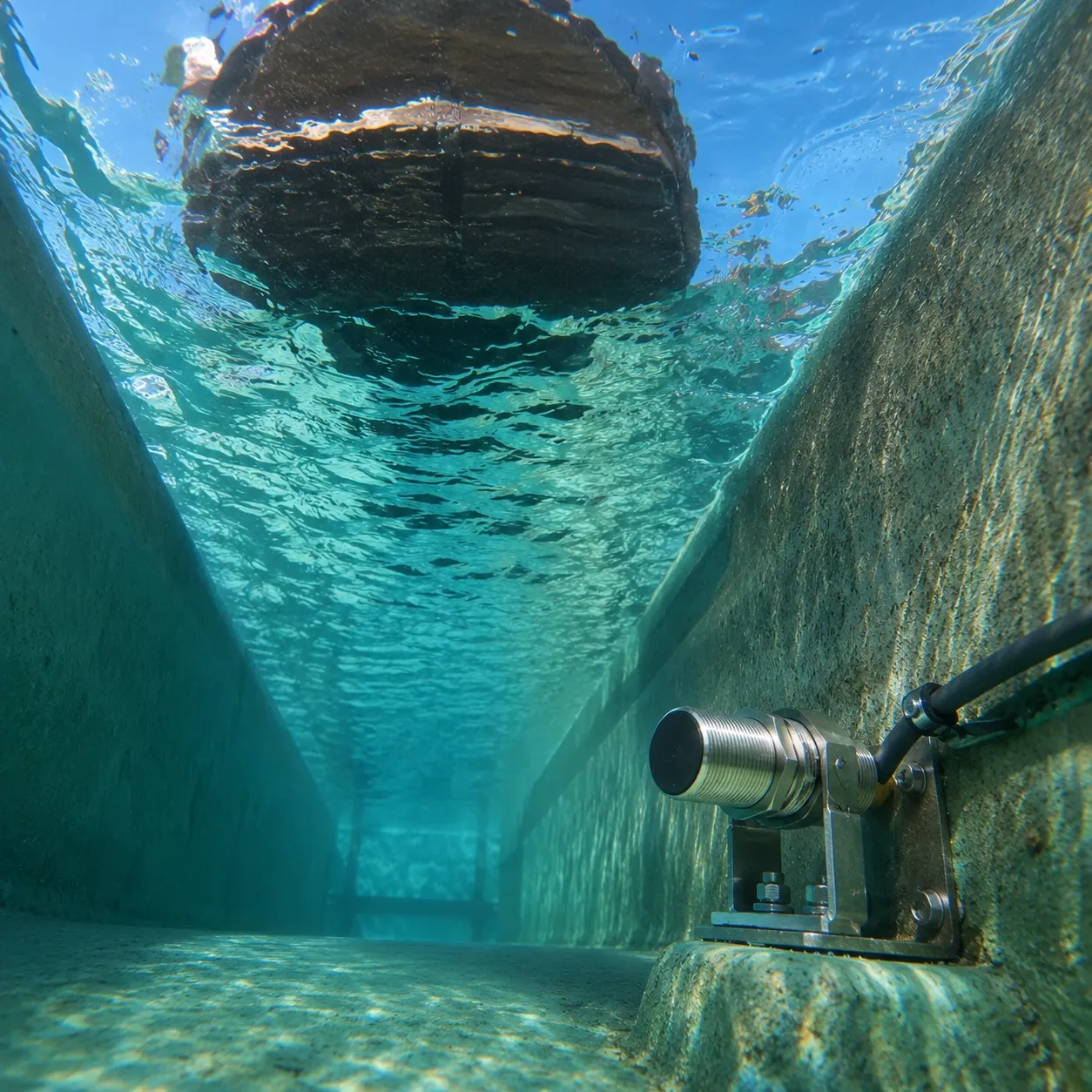 Do not attempt to use reflective mounting configurations in a water ride. Reflectors accumulate algae, mineral deposits, splash residue, and physical wear in water environments at a rate that makes maintenance impractical. A through-beam configuration eliminates the reflector entirely and provides a stronger beam with better penetration through water spray and mist.
Cable Selection and Connector Treatment
Cable connectors are a critical vulnerability in water ride sensor installations. Water intrusion at a connector joint will corrode the pins and eventually disable the sensor.
For any sensor that will be at or near the water level, specify the hard-wired cable version rather than a quick-disconnect style if at all possible. Hard-wired cables have no connector joint at the sensor end — the cable exits the sensor through a sealed cable gland and runs as a single continuous length to the termination point in a dry control enclosure. There is no connector joint to leak.
If quick-disconnect sensors must be used — for example, where easy field replacement without rewiring is a priority — apply dielectric grease generously to the male pins and the connector bore before mating the connectors. Dielectric grease displaces water from the connector interface, prevents moisture from bridging between pins, and inhibits corrosion on the contact surfaces. Reapply dielectric grease at every annual maintenance interval.
Mounting Considerations
Mount sensors in positions that protect them from direct impact by boats, splash guards, and maintenance equipment during normal operation. Sensors struck by boats will be physically destroyed regardless of their IP rating. Use recessed mounting locations, guard rails, or protective brackets to position sensors where they cannot be hit.
Consider the effects of surge and wake from passing boats on sensor alignment. A boat passing through the channel creates a wave that persists for some time after the boat has cleared the sensor zone. If the sensor mounting is not rigid, these waves can vibrate the sensor and cause alignment shifts over a season of operation. Use secure, vibration-resistant mounting hardware and check alignment regularly.
Recommended Sensor Specifications for Water Ride Applications
- Housing: Stainless steel or glass-fiber-reinforced plastic — corrosion-resistant materials that survive chemical water treatment and outdoor UV exposure
- IP rating: IP68 for submerged or flood-risk locations; IP67 minimum for all other positions
- Sensing range: Select a range that provides at least 2x the channel width as margin — excess range translates directly into reserve power margin against mist and spray attenuation
- Beam power: Choose the highest available power level for through-beam pairs in water environments — the additional beam power provides resilience against contamination on the sensor faces
- Cable jacket: Polyurethane (PUR) cable jackets offer better chemical and UV resistance than standard PVC jackets and are preferred for outdoor and chemical-exposure applications
Annual Maintenance Protocol
Water ride sensors should be treated as consumable components with defined replacement intervals rather than permanent installations. Establish a maintenance protocol that includes:
Annual replacement — replace all sensors in the ride at the end of each operating season or at the start of each new season before reopening. A sensor that has operated through a full season in a water ride environment has been exposed to thousands of boat passes, seasonal temperature cycling, UV radiation, chemical water treatment, and sustained moisture exposure. Replacing sensors on a schedule prevents in-season failures rather than reacting to them.
Alignment verification at seasonal startup — after annual replacement and before the ride opens, verify the alignment of every sensor pair and confirm the output with a simulated boat pass through each sensing zone.
Mid-season inspection — perform a visual inspection of all sensors and cables mid-season, cleaning lens faces and checking for physical damage, cable jacket wear, or connector corrosion.
Demo evaluation — before committing to a sensor product for all positions in a new installation, request demo units from the manufacturer and test them in the actual ride environment for a period of time. Evaluation in the actual application is the most reliable predictor of long-term performance. Compare multiple manufacturers side by side if the installation is large enough to justify the comparison.
Investing in the correct sensors, installing them with care, and maintaining them on a disciplined schedule is what keeps water rides operating reliably through long operating seasons — delivering the consistent guest experience that both visitors and operators depend on.